How does PCB flex differ from traditional rigid PCBs
PCB flex differ from traditional rigid PCBs
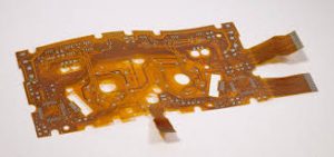
PCB flex is used to reduce manufacturing costs and weight by replacing multiple rigid PCBs, connectors, and cables with one flexible unit. Rigid flex circuits also simplify assembly by eliminating the need for connecting hardware and allowing the board to be bent, folded, or curved as needed. Rigid flex circuits are found in computers, tablets, phones, GPS trackers, and other devices. They also provide a number of additional benefits over rigid boards.
The primary differences between traditional rigid PCBs and flex circuits are that the former have an epoxy or glass-fiber base while the latter uses a polyimide (PI) substrate. The PI film is able to bend and flex, so it’s the ideal material for pcb flex. It also offers resistance to corrosion, humidity, and tears, extending the lifetime of the circuit. The cladding layer is another key difference. While most rigid PCBs use copper-clad laminate (CCL), flex circuits utilize a conductive polyimide film. This material is able to withstand extremely high temperatures without softening or damaging the copper foil.
Another important consideration is the number of layers in a flex circuit. While the layers of a rigid PCB are limited to two, a flex circuit can have as many layers as necessary for its design. It is important to keep in mind, however, that the more layers a flex circuit has, the less flexible it will be. Additionally, high layer counts can create stress points in the traces, which can lead to failure during the bending process.
How does PCB flex differ from traditional rigid PCBs
In order to avoid these problems, it’s important to route traces with the shortest path possible, using fillets to connect wide to narrow traces and avoiding abrupt changes in width where a flex circuit may encounter a stress point. It’s also important to ensure that the traces are routed perpendicular to the bending axis in order to prevent breakage during the flexing process.
A final critical design factor for a flex circuit is determining where to place the rigid-flex transition zone and the hinge area, as well as how to connect the rigid and flex sections of the board. Connector placement is particularly important, as improper connections can cause mechanical stress and signal degradation.
At its core, a PCB flex is a thin, lightweight substrate made of flexible polymer materials such as polyimide or polyester. Unlike traditional rigid PCBs, which are fabricated using rigid substrates like fiberglass or epoxy, flexible PCBs employ materials that enable bending and folding without compromising functionality. The circuitry on a flexible PCB is typically created using conductive traces made of copper, which are etched onto the flexible substrate using specialized manufacturing processes.
Creating a successful flex circuit requires careful planning and following strict rules for manufacturability. In addition, collaborating with PCB manufacturers with experience in both rigid and flex construction can be beneficial. By partnering with a reputable firm like Altium Technology, you can rest assured that your flex circuit will be made according to industry-standard specifications for the best possible results. Start your free trial of Altium Designer today to get started!